The first two concept models (we will call them "Concept-1" and "Concept-2") were visions of a layout that had not yet been built. It would seem that our third model (we will call it "Concept-3") could never be as useful as the first two models, because the freedom to design has now been constrained by the immovable columns and girders of an existing layout.
Surprisingly, it is because of these existing constraints that the development of Concept-3 will proceed more imaginatively and smoothly than the creation of Concept-1 (Plate 15) or Concept-2 (Plate 17).
--more--
Concept-2 (Plate 17) was much more "down to earth" than Concept-1. A spiral gradient now descended from the elevated loop to the valley below, thus offering the possibility of railway operations on two connected levels. However, Concept-2 also failed, because it did not "explain" the existence of a railway within the confines of the layout's framework. A sprawling switchyard, added as an afterthought, was "plunked down" into a free area. An unconvincing river, that appeared to have lost its way, bisected the baseboard. (See Plate 91 for these absurdities.) No provision was made for a locomotive service yard, or for a passenger terminal. The "Flying Scotsman" without a suitable terminal? Unthinkable.
It is clear that Concept-3 will be constructed with an advantage that neither of its predecessors enjoyed. Because actual layout construction is already well under way, there is now less tolerance for conceptual nonsense, such as switchyards in the middle of nowhere or wide rivers that threaten to inundate the landscape.
The prior existence of a functioning, partially-completed layout must never be considered a constraint upon a good designer's vision. Instead, an existing layout is in fact a guide to visualization, just as the mountains, valleys and rivers of the real world steer the civil engineer's decisions to emplace public works (a tunnel here?... a bridge over there?...perhaps a canal in that river valley...).
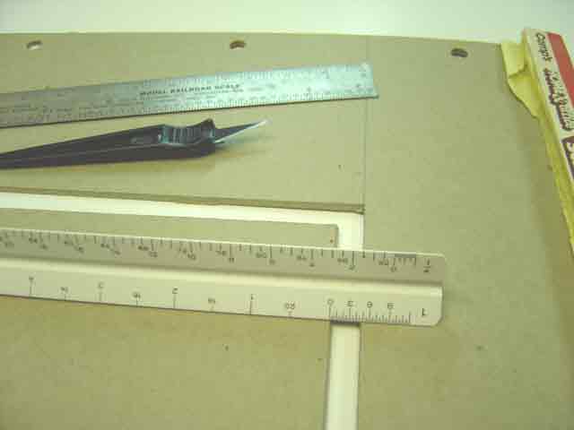
We begin construction of Concept-3 with a one-twelfth scale baseboard that is accurate to the quarter-inch (the baseboard of the actual layout measures eight feet plus a quarter inch - see Plate 212). Incidentally, the accompanying picture reveals why we should always save scrap cardboard.
Go to top of page