This is a lock-controlled canal constructed within a natural gorge. The gorge has a drop of about twenty-five feet (in 00 scale, about 4 inches) from east to west (left to right). The purpose of the lock is to permit barges to rise and descend gradually within the gorge, which, before the lock was built, would have been a dangerous, raging rapids.
--more--
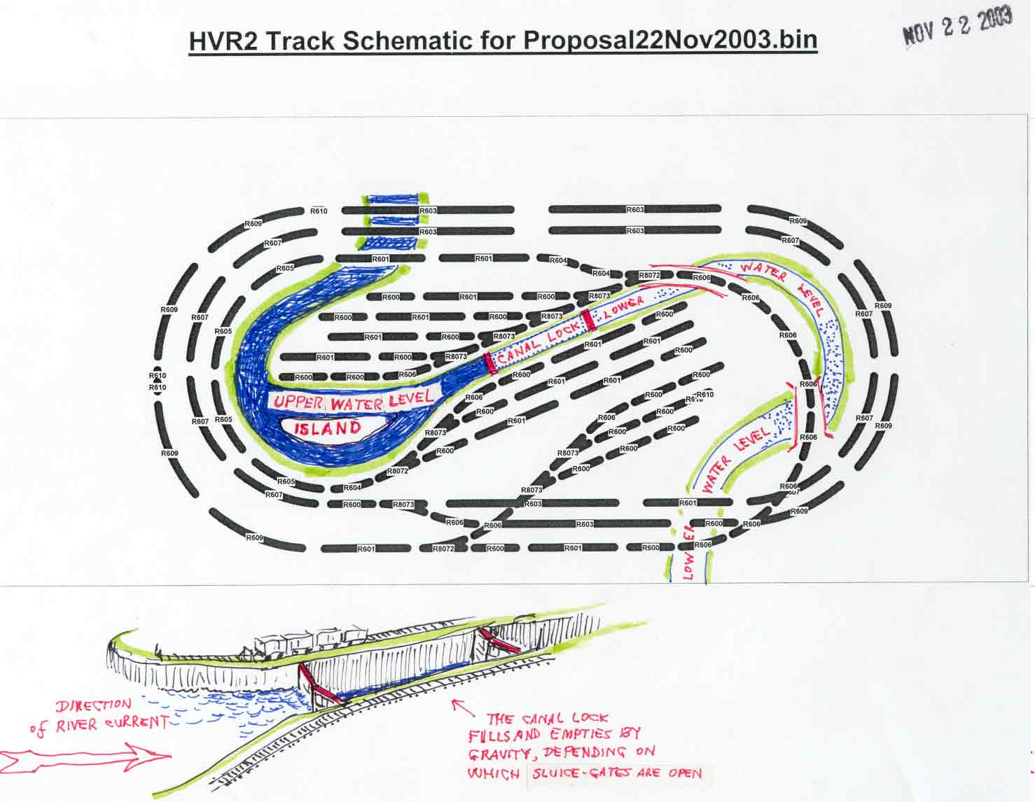
1. The barge, now in the high southern water, stops at the east (left-hand) navigation gate of the lock.
2. Suppose the water inside the lock (which is like a little artificial lake) is at a low level. The lock operator opens an upstream sluice gate and permits water from the left of the lock to pour, by gravity, into the lock, thereby filling the lock to the higher level.
3. The lock operator opens the left-hand (upstream) navigation gate of the lock and the barge propels itself into the lock. When the barge is safely tied up in the lock, the lock operator closes the upstream navigation gate.
4. The lock operator opens a downstream sluice gate and drains the lock, by gravity, into the low-level stream to the right. Gradually, the barge drops to the low level of the downstream canal.
5. The lock operator opens the right-hand (downstream) navigation gate, the barge casts off its safety lines and propels itself out of the lock. When the barge is safely past the downstream navigation gate, the lock operator closes the gate.
The lock works exactly the same if a barge enters the lock from the downstream end. The lock's level is matched to the downstream level through a sluice-gate, the barge enters the lock through the downstream navigation gate, the downstream navigation gate is closed behind the barge, sluice-gates fill up the lock, thus floating the barge to the higher level, the upstream navigation gate is opened, and the barge propels itself out of the lock into the high water.
Go to top of page