--more--
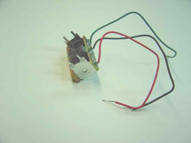
Observe in the accompanying picture that four thin metal tabs are sticking up from the corners of the point motor. These are mounting tabs, and their use is demonstrated in the sequence of plates that follow.
Go to top of page
| For reference books and articles relating to these pages, see our bibliography | ||
| Are you getting tired of looking at trains? Try the Mad Toy Collector's exhibition, or visit The Heraldry Guy! | ||
| Searching for a particular topic in these pages? Try our subject index (updated continually) | ||
| It's all being made into a serialized movie! Click here to watch the movie episodes! | ||
| Go to the Next Plate | Go to the Previous Plate | Go to the Numerical Plate Directory |
Plate 159: Building a locomotive service yard, Part 25: a Hornby R8014 Mark 2 point motor in position for sub-surface mounting
(This plate added OCT 2003)
|
The point motors for the locomotive service yard are to be mounted under the roadbed, as opposed to being mounted upon
the surface of the roadbed, as was the point motor in Plate 99. When mounting a
Hornby R8014 Mark 2 point motor underneath the roadbed, the builder must determine
whether it is practical to make rectangular cut-outs to accommodate the point motor. In this case, because the roadbed of the
service yard consists only of thin, 3/16-inch plywood, rectangular cut-outs are appropriate. However, if the roadbed consists of of a thicker, tougher
material, such as the heavy girder underlying the plywood in Plate 99, surface-mounting becomes more practical.
--more-- |
|
|
Please note that it is possible to mount a Hornby point motor under thick roadbed without making rectangular cut-outs. Hornby provides for the sub-surface
mounting of point motors under thick roadbed by including a long vertical extension arm with every point motor.
However, the extension-arm method is not required in this layout at this time.
Observe in the accompanying picture that four thin metal tabs are sticking up from the corners of the point motor. These are mounting tabs, and their use is demonstrated in the sequence of plates that follow. Go to top of page |
|