For reference books and articles relating to these pages, see our bibliography
Are you getting tired of looking at trains? Try the Mad Toy Collector's exhibition, or visit The Heraldry Guy!
Searching for a particular topic in these pages? Try our subject index (updated continually)
It's all being made into a serialized movie! Click here to watch the movie episodes!
Go to the Next Plate Go to the Previous Plate Go to the Numerical Plate Directory

Plate 154:  Building a locomotive service yard, Part 20:  traction-current characteristics of a Hornby standard point
(This plate added OCT 2003)

Here we see the point (American usage: "switch") that creates the two spurs of the service yard. This close-up view provides us with a chance to investigate the electrical characteristics of a Hornby standard point. The following explanation employs British usage exclusively, in accordance with Hornby's technical specifications.

--more--
It is very clear from this picture that the point blades have been thrown to the curved side of the point, thus providing a straight path for a train approaching from the left. Suppose that the supply of traction current originates from the left of the point as viewed here. In this case, the built-in electrical properties of this point will cut off traction current from the curved side of the point. In other words, if a locomotive were standing upon a spur connected to the curved side of this point, that locomotive would receive no current (again presuming that the only source of current originates from the left of the point).

Likewise, again assuming that the supply of traction current originates from the left of the point, the straight side would receive no traction current if the point blades were thrown to provide a curved path.

This property of Hornby points, that is, the property of providing traction current only to the path to which the point blades are switched, turns out to be extremely useful to the layout designer.

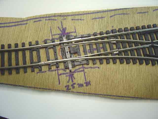
Changing the subject for a moment, the picture happens to show a feature of Hornby points that should be kept in mind. Observe the two long sleepers on either side of the sliding arm that joins the point blades. Each of these long sleepers has a small slot at each end, providing a total of four slots. These slots can be used when installing a subsurface point motor, a topic which is later covered in detail in these pages.

Go to top of page