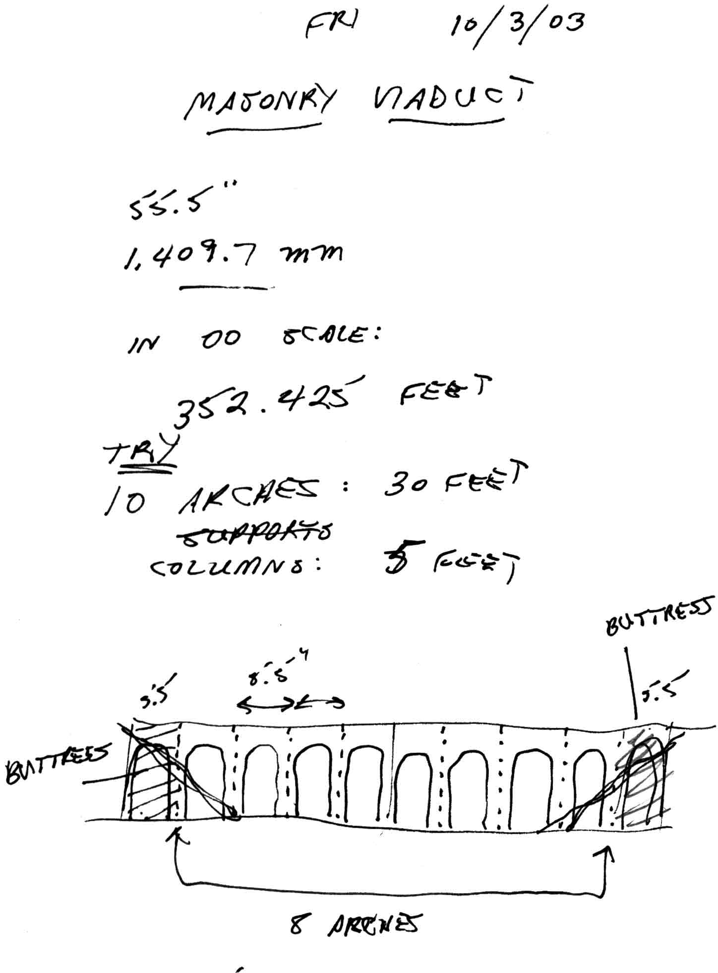
In 00 scale, one inch in the model represents approximately 6 feet 3 inches in full size. The model viaduct (see the accompanying sketch) will reach from the water level up to the 12-inch upper level, resulting in a scale height of 76 feet. (For an explanation of layout levels, see the section "The three levels" in Plate 129.)
The proportions of the arches in the design of the masonry viaduct were influenced by various pictures in the builder's personal library. The particular illustration which most directly inspired the design was in the book "Railways and the Victorian Imagination", by Michael Freeman (1999: Yale University Press). The illustration, on page 81 of Freeman's book, is from a lithograph made in 1848 by A. F. Tait (see Plate 15 for a brief discussion of A. F. Tait). Tait's lithograph represents the Stockport Viaduct in England.
An illustrated discussion of the history and present-day state of restoration of the Stockport Viaduct, published in The Railway Magazine, is cited in our bibliography (click here for the citation).
--more--

In keeping with the desired proportions of the proposed viaduct, a total of 10 arches was originally planned. Each arch would be 5 inches wide, separated from the next arch by a one-inch thick column. In 00 scale, a 5-inch arch represents a span of about 30 feet, and a one-inch column represents a thickness of about 6 feet.
As can be seen in the accompanying sketch, only 8 of the 10 original arches were kept in the final design. The arches at each end of the viaduct were replaced by solid masonry buttresses in keeping with actual viaduct construction.
Go to top of page