For reference books and articles relating to these pages, see our bibliography
Are you getting tired of looking at trains? Try the Mad Toy Collector's exhibition, or visit The Heraldry Guy!
Searching for a particular topic in these pages? Try our subject index (updated continually)
It's all being made into a serialized movie! Click here to watch the movie episodes!
Go to the Next Plate Go to the Previous Plate Go to the Numerical Plate Directory

Plate 132:  Planning a masonry viaduct, Part 2
(This plate added OCT 2003)

In Plate 131 we showed a preliminary sketch of the design for a 00-scale masonry viaduct to be positioned at the south face of the layout along the upper-level girder. From the sketch, the designer drew a "cartoon" of the viaduct model. In the sense used here, a cartoon is defined as a full-size drawing to be used as a pattern for another work, such as a mosaic, painting or tapestry. In this case, the cartoon is a full-size drawing of a model viaduct.

--more--
The cartoon was drawn on paper from an artist's newsprint pad. The newsprint pad contained sheets measuring 24 inches by 36 inches, so a 36-inch sheet was removed from the pad and cut lengthwise to obtain two half-sheets, each 12 inches by 36 inches.  The 12-by-36 half-sheets were then taped together with Scotch Magic Tape (c) to a total size of 12 inches by 72 inches, and then trimmed to 12 inches by 55-1/2 inches. The 12-inch dimension corresponds to the height of the model viaduct, and the 55-1/2 inch dimension corresponds to the total span of the model.

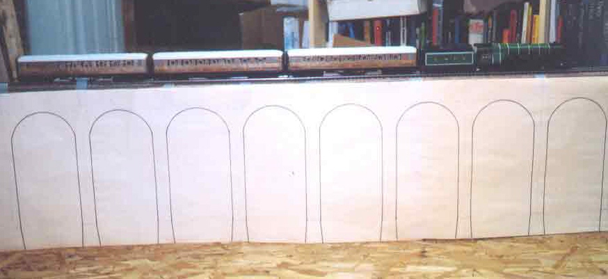
Using a drafting compass and a straight edge, the designer drew the outline of each arch in pencil.  The pencil outlines were then inked over with a heavy black marker, and the resulting cartoon was suspended from the upper-level roadbed of the south face with Scotch Magic Tape (c).  In the cartoon, each arch is five inches wide, and each column is one inch wide, corresponding respectively to arches with a 30-foot span separated by 6-foot-thick columns.

This view shows the entire "Flying Scotsman" train posing stationary on the roadbed at the top of the cartoon. If you look closely at the columns, you can see that they taper and widen slightly at the bottom.  This increased width represents the column footings, as depicted by A. F. Tait in his lithograph of the Stockport Viaduct (see Plate 131).

Go to top of page