The three levels:
Level 1: The"upper level"
The upper level, at a height of 12 inches (equivalent to 76 feet in 00 scale), is marked in solid red. This level comprises a complete continuous-running loop and the topmost part of an outer descending spiral (see Plate 52, for example).
--more--
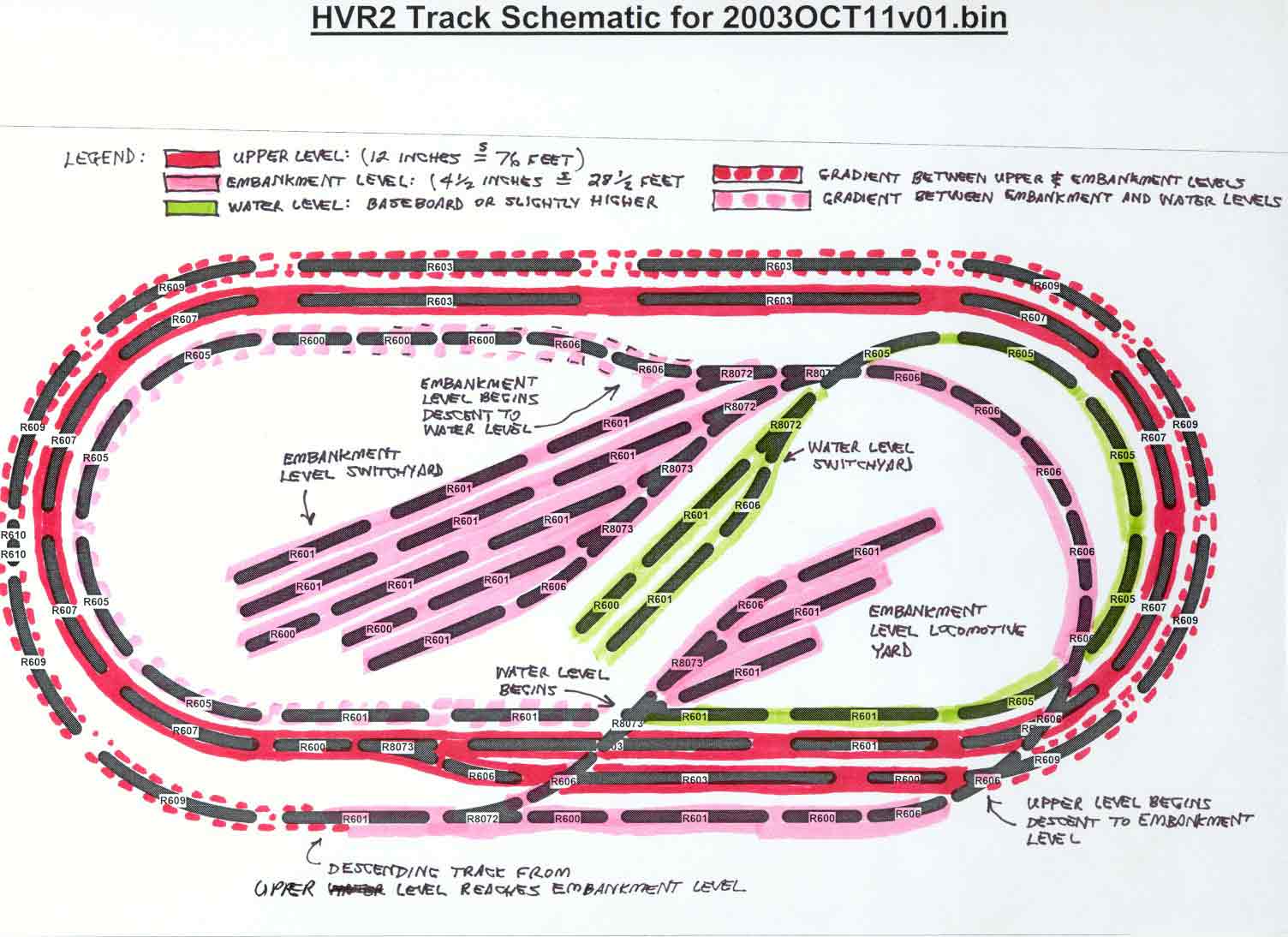
The embankment level, at a height of 4-1/2 inches (equivalent to about 28 feet in 00 scale), is marked in solid pink. This level comprises a locomotive yard as well as a main switching yard. The locomotive yard was introduced in Plate 123. The proposed main switching yard has not yet been discussed in any detail, although Plate 127 briefly refers to a "car yard".
Level 3: The "water level"
The water level, at a height of an inch or less (6 feet or less in 00 scale), is marked in solid light green. This level comprises a small-radius loop connecting to a small switching yard. The small-radius curved track used at the water level is generally negotiable only by short-wheelbase locomotives. The "Flying Scotsman", for example, might get stuck if it tried to negotiate such tight curves.
The two gradients:
Gradient 1: The upper-to-embankment gradient
The upper-to-embankment gradient is marked in dotted red. Starting at the 12-inch upper level, this gradient (or "slope") begins at the lower right-hand corner of the diagram, where the upper level begins a gradual descent to the embankment level. After almost a complete circuit of the layout, the gradient ends at the lower left in the diagram, leveling off at the 4-1/2 inch embankment level (see Plate 80, for example).
Gradient 2: The embankment-to-water gradient
The embankment-to-water gradient is marked in dotted pink. The purpose of this proposed gradient is to enable the movement of freight cars (British usage: "goods wagons") between a barge-canal port at the water level and the main switching yard at the embankment level. This gradient, which consists of the same small-radius curves employed at the water level, would generally be negotiable only by short-wheelbase locomotives.
Go to top of page