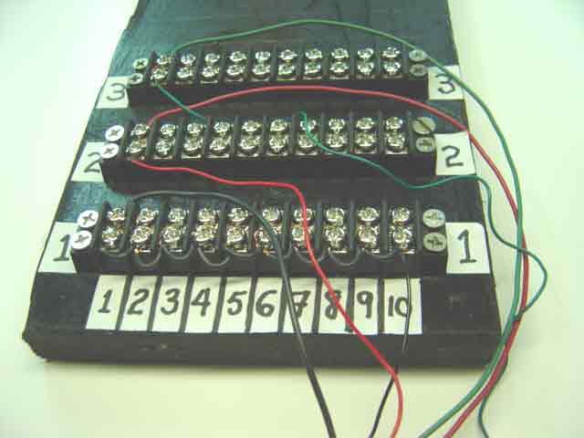
The accompanying picture shows the power distribution board with all circuits installed for the point motor at location ULML-pt-1. The red wire at the top half of the terminal block at row 2, column 1, is an equipment wire. It is connected to the "red" solenoid of a point motor at the other end. The red wire at the bottom half of the same block in column 1 is a control wire. It is connected to a passing contact lever switch at the other end. Likewise, the two green wires on block 3 are similarly connected.
The wiring arrangement illustrated here is unsatisfactory, because the wires are not laid out in orderly channels. One reason we provided separations between adjacent terminal blocks was to permit the wires to lie between the blocks in neat channels. However, it requires more than merely separating the blocks from each other to force the wires to line up into orderly channels.
|
|