--more--
The reason for numbering the "rows" and "columns" is to provide the builder with a quick means of finding electric circuits (a "circuit" is the total path taken by an electric current as it does its work).
Eventually, a Guidebook with a Table of Names
The builder will eventually possess an operational guidebook for the layout. In this guidebook, all the electrical devices (such as point motors) will be captioned with everyday names, such as "embankment-level locomotive yard throat point", or "water-level yard point number 1". These names will then be written in a table of names. Along with each name, the table will contain clearly detailed functional information pertaining to that particular device. Here is an example of a table entry describing the electric circuits for the sub-surface point motor at the throat of the embankment-level locomotive yard:
Name on Map: Embankment-level locomotive yard throat point ELLY-Pt-1
Common solenoid circuit: Row 1, Column 3
Solenoid circuit that switches throat-point to spurs ELLY-Sp-A and ELLY-Sp-B: Row 2, Column 3
Solenoid circuit that switches throat-point to spur ELLY-Sp-C: Row 3, Column 3
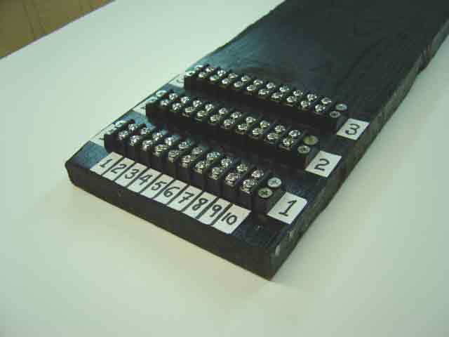
Any of these three "circuits" (wires) can then easily be found in the power distribution board because it is a simple matter to locate each row and each column.
Note: The method by which we actually find a particular row and a particular column is known to computer people as the indexed sequential access method. This means simply that the row numbers are "indexes", which are big numbers that anyone can see immediately at a glance. Therefore, we say that each terminal block is "indexed" with a row number. However, the individual screws in a terminal block are not marked with big index numbers, because they are crowded too close together. Instead, we placed a sequential guide with the numbers 1 through 10 on the front of the distribution board. This guide reminds the person looking at the board that he must count the screws, from left to right in each block, to be certain of finding a particular "column". In the example given above, the wire carrying the solenoid current that switches the yard-throat point to spurs A and B can be found by going directly to "row 2" (terminal block 2), and then counting the screws on block 2 from the left: "one, two, three", which means "column 3". This combination of indexing and sequencing (counting) is, as we said, known to computer people as the Indexed Sequential Access Method, commonly abbreviated as ISAM.
Go to top of page