The diagram in Plate 129 shows all the point motors that were proposed for the entire layout at that time: a total of 10 point motors. There is a single point motor at the upper level, 8 motors at the embankment level, and a single motor at the water level. The accompanying wiring diagram accommodates all of these 10 proposed point motors. The scheme embodied in this diagram is not, however, limited to 10 point motors; it is easily expandable to any number of point motors.
--more--
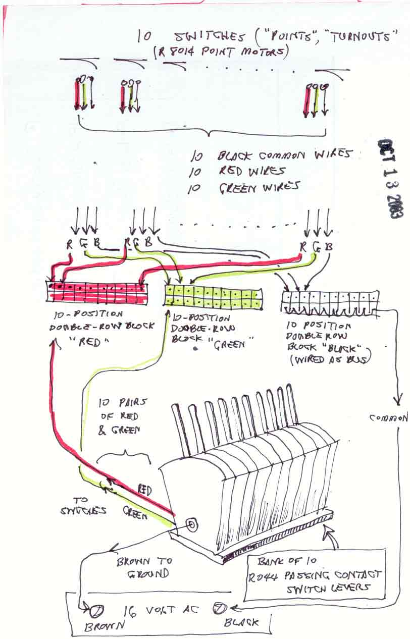
1. The point motors
The 10 point motors are indicated at the top of the sketch. Each point motor is accompanied by a "triplet" of wires: red, green, and black. Because there are ten proposed point motors, there is therefore a total of 10 red wires, 10 green wires, and 10 black wires issuing from the various places in the layout where the point motors are installed.
2. Gathering the wires by color at the terminal blocks
In the middle of the sketch are three 10-position terminal blocks. A terminal block is a device that permits wires from all over the layout to be neatly gathered in one place. There are three terminal blocks because there are three different colors of wire. The "red" terminal block gathers all 10 red wires from the point motors, the "green" block gathers all the green wires, and the "black" block gathers all the black wires. Each block then "distributes" the red, green and black wires from the point motors to their correct places in the bank of lever switches and elsewhere.
3. Distributing the wires from the red, green and black terminal blocks to their correct destinations
After the red, green and black wires from the point motors are fastened down onto their respective terminal blocks, other wires must then be matched up to the point-motor wires. For example, the diagram shows a red wire from the point motor at the top left attached to the first position in the top row of the red terminal block. A matching red wire from the leftmost of the 10 lever switches at the bottom of the diagram runs up to the first position in the bottom row of the red block, where it is electrically connected to the red wire from the first point motor.
In this way, all the red and green wires from the point motors are matched to the red and green wires from the lever switches in the switch bank. The black wires, however, are not connected exactly in this way. The top row of the black terminal block gathers all the black wires from the point motors, but there is only one black wire that emerges from the bottom row of the block. This means that the bottom row of the black terminal block is "bus wired". Bus-wiring means that all 10 positions at the bottom of the black terminal block are electrically joined together into a single black wire. This single wire connects to one of the AC binding posts of the Hornby R965 Standard Train Controller. Finally, the single brown wire from the R965 controller attaches to the leftmost of the 10 lever switches.
Go to top of page