For reference books and articles relating to these pages, see our bibliography
Are you getting tired of looking at trains? Try the Mad Toy Collector's exhibition, or visit The Heraldry Guy!
Searching for a particular topic in these pages? Try our subject index (updated continually)
It's all being made into a serialized movie! Click here to watch the movie episodes!
Go to the Next Plate Go to the Previous Plate Go to the Numerical Plate Directory

Plate 165:  Building a locomotive service yard, Part 31:  how to install a lever switch for an additional point motor
(This plate added OCT 2003)

When the point motor was installed and wired for the service yard, the red and green wires from the point motor needed to be connected to a new R044 passing contact lever switch.

Reminder:

Each point motor requires a separate lever switch. Don't forget to obtain an R044 lever switch for every point motor that you install.)

After the red and green wires from the service yard's point motor were connected to the new lever switch, the new lever switch was then joined directly to an existing lever switch (at this time, the only existing lever switch was the one that controls the upper-level point). This procedure of directly plugging a new lever switch into an existing lever switch results in a "bank" of lever switches.

--more--
The beginnings of our lever-switch "bank" is illustrated in the picture. Every lever switch contains posts and sockets to facilitate joining the lever switches together. One of the advantages of creating a bank of lever switches is that the entire bank works through a single brown wire from the train controller. When a lever switch plugs into a bank of lever switches, the current from the brown wire is automatically applied to any other lever switch in the bank. The brown-wire current passes through the bank of lever switches through the little brass plugs and sockets near the base of each lever switch.

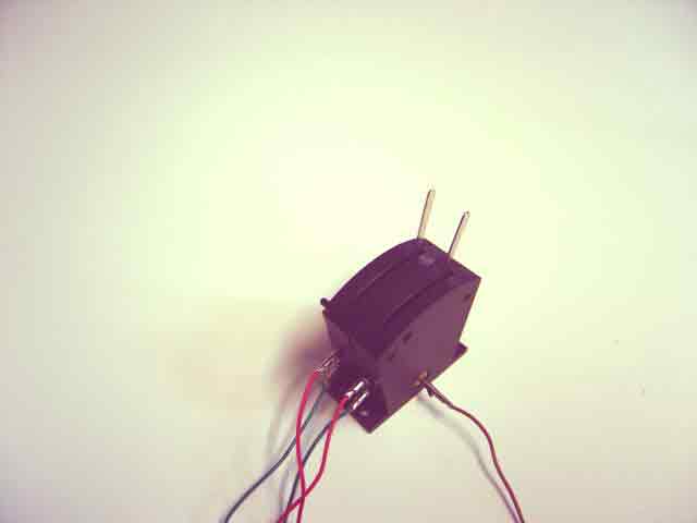
The lever switch at the lower right is the original lever switch for the upper-level point. The lever switch for the service-yard point is the leftmost of the two switches, and is joined directly to the original lever switch. Observe that the brown wire is still plugged into the base of the original lever switch. Only one brown wire is required to serve the entire bank.

A small black "knob" can be seen protruding from the upper left corner of the lever bank. This is one of the "keys" that permit the lever switches to be aligned and fastened into a bank.

Go to top of page