We have now permanently connected the red and green solenoid wires of the R8014 point motor at location ULML-pt-1 to 3-foot lengths of 22-gauge red and green hook-up wires. All the soldering and testing procedures described in previous plates were followed rigorously during the hook-up process. The builder has learned, after many years of wiring experience, that neglecting these procedures can easily lead to "mysterious" device malfunctions. It cannot be urged too strongly that proper soldering and testing procedures must be obeyed during every step of a circuit hook-up. The amount of extra time spent performing the step-by-step procedures is small compared to the time required to troubleshoot a poorly implemented circuit.
The accompanying picture illustrates why it is a good idea to insulate all soldered joints thoroughly with electrician's tape. Observe that the insulated joints are almost touching each other. If these joints were not insulated, intermittent short circuits could easily occur, thereby creating a troubleshooter's nightmare.
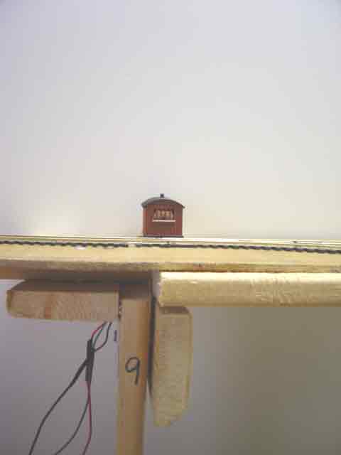
The small structure above the roadbed is a 00-scale trackside hut that is provided with the Hornby point motor housing kit.
|
|