For reference books and articles relating to these pages, see our bibliography
Are you getting tired of looking at trains? Try the Mad Toy Collector's exhibition, or visit The Heraldry Guy!
Searching for a particular topic in these pages? Try our subject index (updated continually)
It's all being made into a serialized movie! Click here to watch the movie episodes!
Go to the Next Plate Go to the Previous Plate Go to the Numerical Plate Directory

Plate 231:  Wiring the point motors through the distribution center, Part 9: a circuit table in the guidebook
(This plate added NOV 2003)

In Plate 226, we said that the everday names of electrically-operated devices (such as point motors) would be put into a table, which would relate the guidebook's diagrams to circuit numbers in the power distribution center. The accompanying picture shows three table-entries that constitute a complete wiring description for "Upper Level Main-Line Point Number 1" (abbreviated ULML-pt-1). See Plate 230 for the relevant operating diagram and Plate 100 for a picture of the actual point.

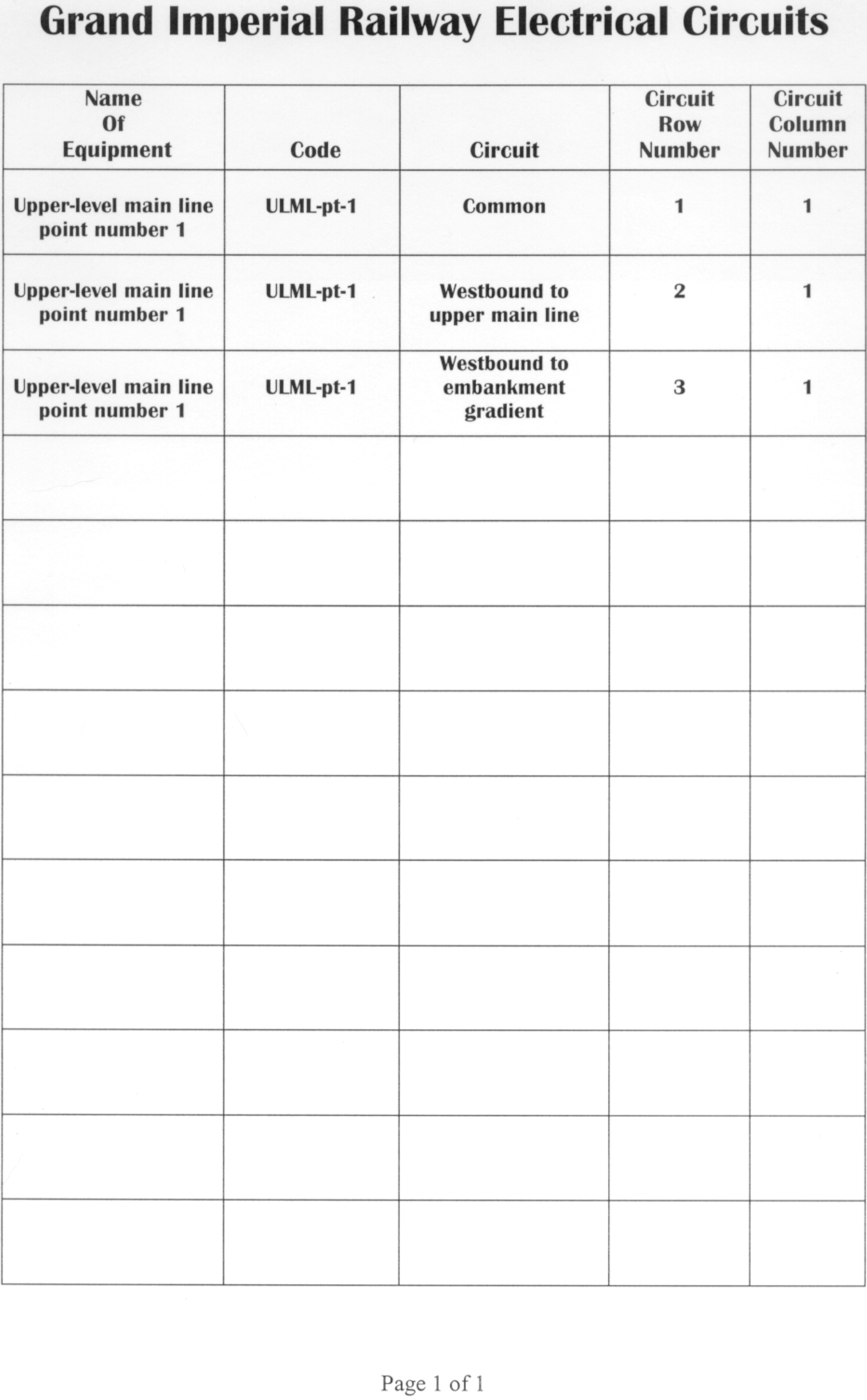
The descriptions of the point-motor circuits (in the column headed "Circuit") are not written from a technician's viewpoint, such as "Point motor solenoid on red wire". Instead, the circuit descriptions are operational, meaning that the descriptions pertain to the work done by the circuit, not to the electrical details of the circuit.

For example, the first entry ("Common") means that the "common return" wire of the point motor is connected to the power distribution center at row 1, column 1. The second entry ("Westbound to upper main line") means that the wire at row 2, column 1 causes the point to switch a westbound train to the main line of the upper level. The third entry ("Westbound to embankment gradient") means that the wire at row 3, column 1 causes the point to switch a westbound train to the down-grade leading to the embankment level.