--more--
Go to top of page
| For reference books and articles relating to these pages, see our bibliography | ||
| Are you getting tired of looking at trains? Try the Mad Toy Collector's exhibition, or visit The Heraldry Guy! | ||
| Searching for a particular topic in these pages? Try our subject index (updated continually) | ||
| It's all being made into a serialized movie! Click here to watch the movie episodes! | ||
| Go to the Next Plate | Go to the Previous Plate | Go to the Numerical Plate Directory |
Plate 201: Installing a surface-mounted point motor with an extension arm, Part 16
(This plate added NOV 2003)
|
In Plate 195, we saw that two holes had been made in the roadbed for admitting
the red, green and black wires from the point motor. We stated that only one of the
holes would be used; the
following paragraph explains why this is true.
--more-- |
|
|
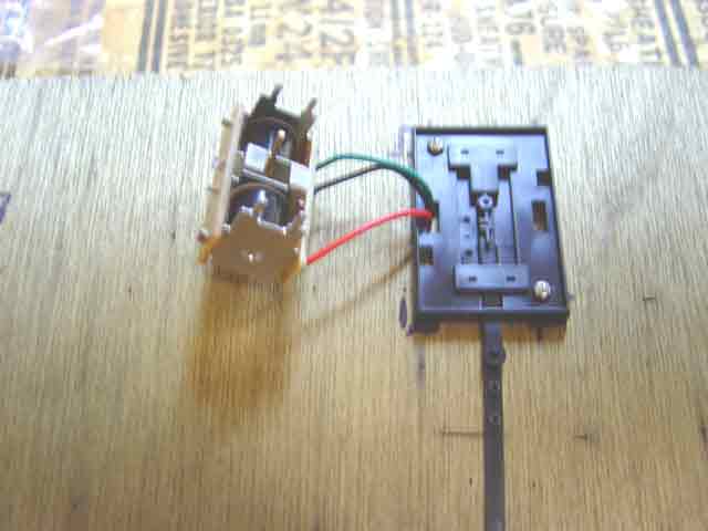
Observe that the red, green and black wires all originate on the same side of the point motor, so all
three wires should be drawn through the hole that is directly under the wire-side of the motor. We happened to choose
the hole on the left. However, we might just as easily have rotated the point motor 180 degrees and drawn the wires through the hole on the right.
It doesn't make any difference, because the throwing-direction of an R8014 Mark 2 point motor is controlled by
how the red and green wires plug into the R044 lever switch. The point motor's physical orientation is not
an important consideration (see the operational testing sequence beginning at
Plate118).
Go to top of page |
|