| For reference books and articles relating to these pages, see our bibliography | ||
| Are you getting tired of looking at trains? Try the Mad Toy Collector's exhibition, or visit The Heraldry Guy! | ||
| Searching for a particular topic in these pages? Try our subject index (updated continually) | ||
| It's all being made into a serialized movie! Click here to watch the movie episodes! | ||
| Go to the Next Plate | Go to the Previous Plate | Go to the Numerical Plate Directory |
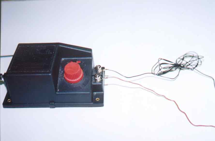
Plate 108: Installing a Hornby Point Motor: where the wires go, Part 4
(This plate added OCT 2003)
| This view is similar to Plate 107, but the black and brown wires have both been screwed down onto the two AC constant voltage binding posts of the R965 controller. It doesn't matter which binding posts you choose for the black and brown wires, as long as each wire is connected to a different post. |
|