| For reference books and articles relating to these pages, see our bibliography | ||
| Are you getting tired of looking at trains? Try the Mad Toy Collector's exhibition, or visit The Heraldry Guy! | ||
| Searching for a particular topic in these pages? Try our subject index (updated continually) | ||
| It's all being made into a serialized movie! Click here to watch the movie episodes! | ||
| Go to the Next Plate | Go to the Previous Plate | Go to the Numerical Plate Directory |
Plate 107: Installing a Hornby Point Motor: where the wires go, Part 3
(This plate added OCT 2003)
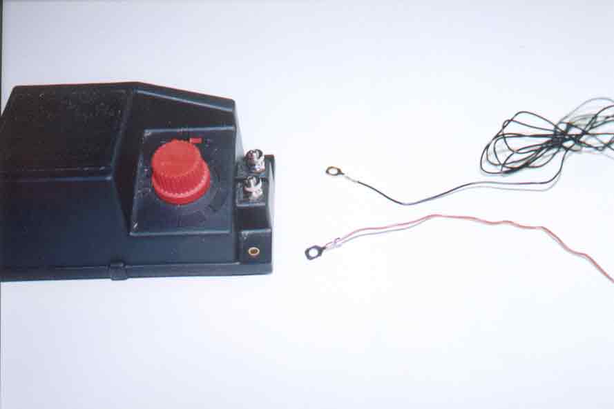
| This view shows one end of the black and brown wires that are packaged with the R044 Passing Contact Lever Switch. The two wires are laid out alongside the R965 Standard Train Controller. The ends of the wires that are shown here are both fitted with ring-type lugs. The other ends of the two wires are not visible in this view. Only one end of each wire is fitted with a ring-type lug; the other end of each wire is fitted with a thin hollow plug. |
|