--more--
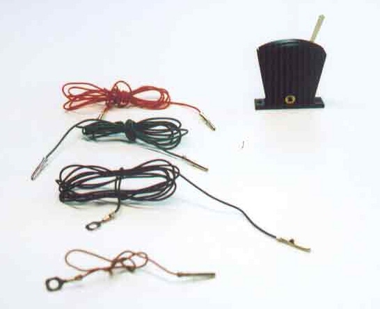
This wire is intended to connect the R044 lever switch to the red wire of the R8014 Point Motor (see Plate 104).
(2) Green wire
This wire is intended to connect the R044 lever switch to the green wire of the R8014 Point Motor (see Plate 104).
(3) Black wire
This wire is intended to connect the R8014 point motor to either one of the AC constant-voltage binding posts of the R965 Standard
Train Controller. The black wire does not connect directly to the lever switch.
(4) Brown wire
This wire is intended to connects the R044 lever switch to the other AC binding post of the R965 Standard Train Controller.
Please note that in this view, the lever switch has been turned around so that it is seen from the opposite side
from the way it was shown in Plate 105. In Plate 105, a small brass plug can be seen protruding horizontally from the base
of the lever switch. In this view, showing the opposite side of the unit, we see, instead of a brass plug, a small
brass socket. All subsequent views in this wiring sequence will show this side (the socket side) of the lever switch.
Go to top of page