(1) The transformer
The black box in the left background, with the two brass blades sticking up, is a Scalextric C977 13-volt transformer. Hornby provided a similar transformer in the "Flying Scotsman" train set, but it was a British-style unit that operates upon 230 volts of house current.
--more--
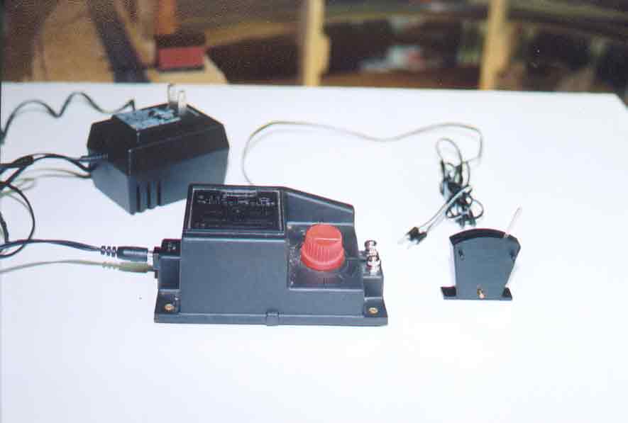
(2) The controller
The large black box in the foreground, with the red knob, is the Hornby R965 Standard Train Controller, which was shown in Plate 79. The C977 transformer from Udisco plugs directly into the R965 unit in exactly the same way as the 230-volt transformer that was shipped with the "Flying Scotsman". (The small C977 13-volt plug can be seen connected to the left of the R965.) The thin black cable coiled up at the right of the R965 controller carries the 12-volt DC variable current to the train tracks through a Hornby power-connecting clip (see Plate 59). The two silver knobs on the right of the controller are AC constant-voltage binding posts.
(3) The lever switch
The black fan-shaped object on the right is a Hornby R044 Passing Contact Lever Switch. This lever switch is not connected to anything in this view. The R044 is sold with four color-coded wires; these colored wires will be discussed in detail throughout the following series of plates.
Go to top of page