For reference books and articles relating to these pages, see our bibliography
Are you getting tired of looking at trains? Try the Mad Toy Collector's exhibition, or visit The Heraldry Guy!
Searching for a particular topic in these pages? Try our subject index (updated continually)
It's all being made into a serialized movie! Click here to watch the movie episodes!
Go to the Next Plate Go to the Previous Plate Go to the Numerical Plate Directory

Plate 104:  A simplified schematic diagram of the Hornby R8014 Point Motor
(This plate added OCT 2003)

This is a simplified schematic diagram of the Hornby R8014 Mark 2 Point Motor, sketched by the layout's builder. A more accurate diagram, explaining the solenoid concept, appears in Plate 113. The Hornby point motor contains only one moving part: an "iron rod" (it might not really be iron, but we're calling it an "iron rod" because everyone knows that iron is attracted to magnets). The "iron rod" (actually a thin, gold-colored shiny metal rod) can be seen sticking up from the middle of the point motor in Plates 102 and 103. The rod is free to slide sideways between the two electromagnets shown in the diagram.

Note: an electromagnet is a coil of wire that becomes magnetized when electric current runs through the coil. When the current stops, the coil is no longer magnetized. This is a well-known fact of nature that was discovered by the famous physicist Hans Christian Oersted way back in the year 1820, while he was teaching an evening class in Denmark.

--more--
One of the electromagnetic coils is connected to a green wire. The other coil is connected to a red wire. Both coils are connected, in the middle, to a black wire (the common wire).

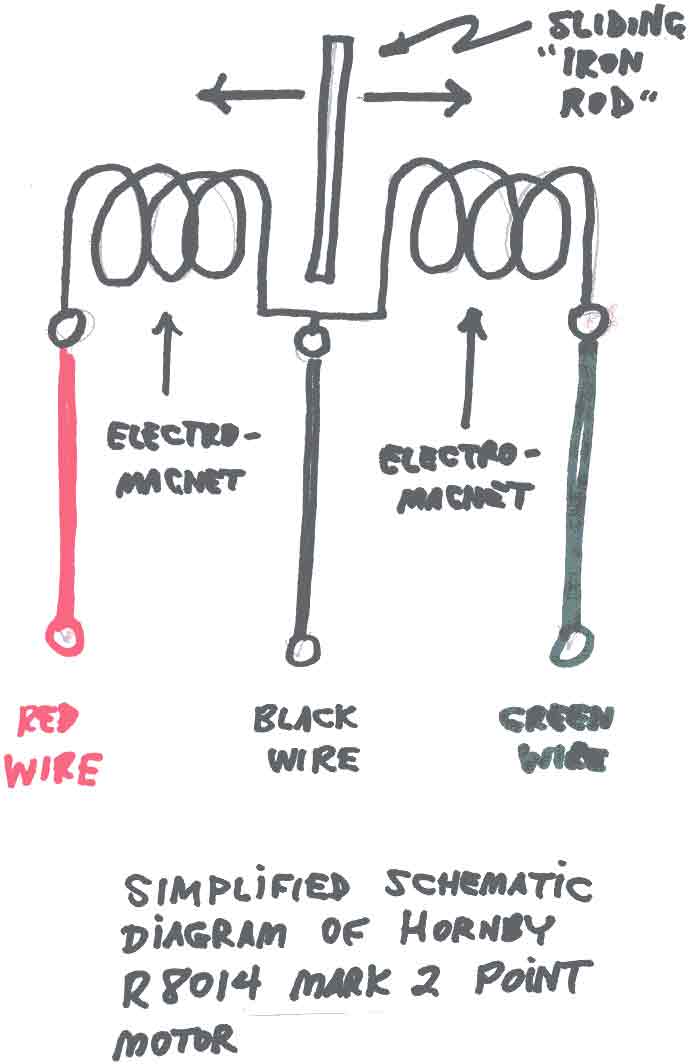
Please look at the schematic diagram. When all three wires are properly connected to a source of current, such as the 16-volt AC terminals of a Hornby controller, current can be forced to run through either the red wire or the green wire. When current runs through the red wire, the coil on the left becomes magnetized, thereby pulling the "iron rod" to the left. Likewise, when current runs through the green wire, the "iron rod" is pulled to the right.

The purpose of the black wire is to guide the coil-current back to the Hornby controller after the current runs through either the red coil or the green coil. If the black wire (the "common wire") were not there, the current wouldn't run at all - every electric current must have a "return path" to the source (this is another fact of nature).

Go to top of page