The continuity test works like this:
--more--
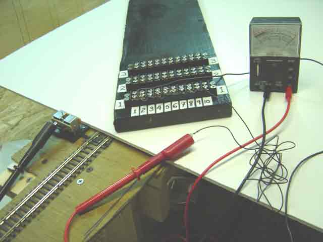
2. The current runs through the red lead and enters the "wriggly" common wire at the red clip.
3. The current runs through the "wriggly" common wire into the terminal position at row 1, column 10.
4. The current runs through all nine jumper wires from column 10 to column 1.
5. At column 1, the current leaves the last jumper wire and "bridges" across to the second terminal screw at that position. Remember that every position in a terminal block has two screws that are electrically joined by a permanent metal bridge.
6. The current leaves the second screw at column 1 and runs all the way through the 3-foot hook-up wire. You can see the hook-up wire running behind the tester and then disappearing from our view at the right-hand side of the picture.
7. The current leaves the hook-up wire at the place where the hook-up wire is soldered to the common solenoid wire. You can't see our soldered joint in this picture because it is concealed beneath the roadbed.
8. The current enters the point motor's common solenoid wire at our soldered joint.
9. The current runs through the point motor's short common solenoid wire and emerges at the factory-soldered connection on the left side of the motor, where it then enters the clip of the tester's black lead.
10. The current runs through the black lead of the tester and re-enters the internal tester battery at the place where the black lead plugs into the tester.
11. The current runs through the tester's internal battery and emerges at the place where the red lead is plugged into the tester. This completes the continuity circuit. The fact that the meter in the tester is "deflected" to the zero-ohms position proves that the current is actually running with zero resistance. This means we have perfect continuity for the common circuit in point motor ULML-pt-1.
Go to top of page