--more--
The two black wires that are attached to the distribution board will be explained in Plate 249.
Go to top of page
| For reference books and articles relating to these pages, see our bibliography | ||
| Are you getting tired of looking at trains? Try the Mad Toy Collector's exhibition, or visit The Heraldry Guy! | ||
| Searching for a particular topic in these pages? Try our subject index (updated continually) | ||
| It's all being made into a serialized movie! Click here to watch the movie episodes! | ||
| Go to the Next Plate | Go to the Previous Plate | Go to the Numerical Plate Directory |
Plate 247: Wiring the point motors through the distribution center, Part 25: the power distribution center moved to a maintenance location
(This plate added NOV 2003)
|
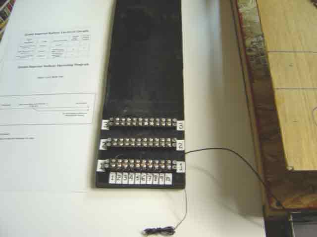
If you refer to Plate 220, you will observe that we intend to place the power distribution board into a sliding "drawer" that resembles the lower floor of a 00-scale power station. The reason for building a sliding "drawer" is that we must remove the distribution board from its place of concealment under the embankmen-level roadbed whenever we need to inspect or change the wiring. The accompanying picture shows the distribution board moved from its "home" position under the roadbed onto a movable maintenance platform alongside the layout. When the board is actually placed into a sliding "drawer", the entire drawer will slide out onto the maintenance platform.
--more-- |
|
|
In the accompanying picture, the northeast corner of the layout is to the right of the maintenance platform. You can see the embankment-level roadbed, which is the future site of the 00-scale power station sketched in Plate 220. "North" is at the bottom of the picture, "east" is at the left.
The two black wires that are attached to the distribution board will be explained in Plate 249. Go to top of page |
|