--more--
Go to top of page
| For reference books and articles relating to these pages, see our bibliography | ||
| Are you getting tired of looking at trains? Try the Mad Toy Collector's exhibition, or visit The Heraldry Guy! | ||
| Searching for a particular topic in these pages? Try our subject index (updated continually) | ||
| It's all being made into a serialized movie! Click here to watch the movie episodes! | ||
| Go to the Next Plate | Go to the Previous Plate | Go to the Numerical Plate Directory |
Plate 176: Building a locomotive service yard, Part 42: the second point-motor cut-out in the permanent roadbed
(This plate added OCT 2003)
|
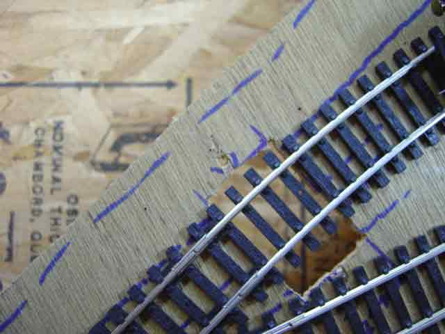
The accompanying picture is similar to Plate 169, except that instead of seeing the photographer's white
backdrop board directly beneath the cut-out, we see all the way down to the baseboard, 4-1/2 inches below. This picture reveals
how simple it is to prepare for the installation of sub-surface point motors if care is taken in planning the positions
of the 25-by-40 millimeter cut-outs.
--more-- |
|
|
When it is time to install a standard right-hand point in this position,
the point motor will first be affixed to the new point by means of the mounting tabs (see Plate 163),
then the curved place-holder track will be removed, and finally the point motor will simply be dropped into the cut-out
with the point already attached.
Go to top of page |
|