For reference books and articles relating to these pages, see our bibliography
Are you getting tired of looking at trains? Try the Mad Toy Collector's exhibition, or visit The Heraldry Guy!
Searching for a particular topic in these pages? Try our subject index (updated continually)
It's all being made into a serialized movie! Click here to watch the movie episodes!
Go to the Next Plate Go to the Previous Plate Go to the Numerical Plate Directory

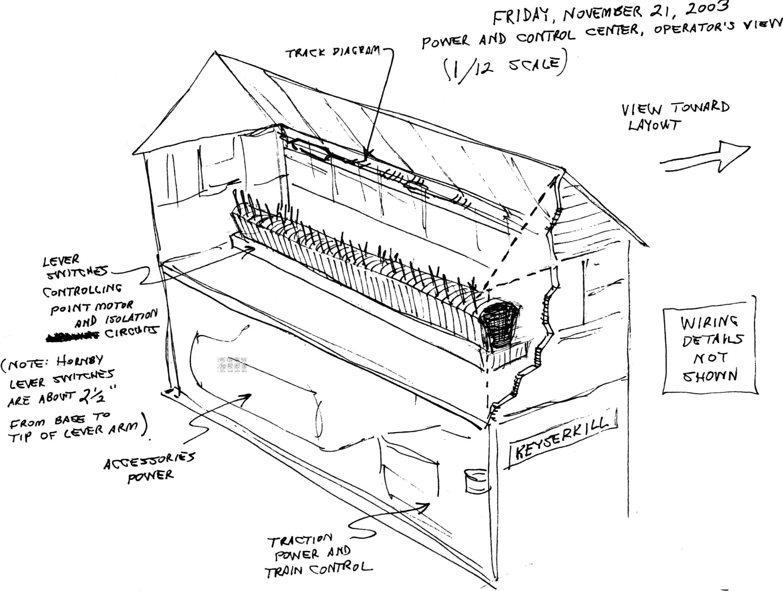
Plate 261:  Rear view and Interior of the power-and-control "signal box"
(This plate added NOV 2003)

The sketch shown here represents the reverse side of the "signal box" shown in Plate 260. The structure contains two floors. The lower floor holds the R965 Standard Train Controller and the Railpower 1440 controller (which is being used here as a low-voltage AC power source). The upper floor contains a bank of Hornby lever switches. This bank will probably contain not only R044 point-motor lever switches but also some R047 isolation lever switches, by means of which various sections of track can be electrically switched on and off.

--more--
The structure will be open in the back (dollhouse style), so that the operator can reach the levers and control knobs within. Also, the entire roof, or at least the rear section, will be removed during operations to provide unhindered access to the lever bank.

In Plate 259, we mentioned that we lengthened the short brown wire from the R044 lever bank by soldering a length of hook-up wire to the brown wire. The accompanying picture shows why this will be necessary. The brown wire from the lever bank must reach one of the low-voltage AC connectors on the back of the Railpower 1440 controller. Since the lever bank will be on the top floor and the Railpower 1440 will be on the lower floor, the brown wire needed to be extended to provide the extra "reach" to bridge between the two floors.

Go to top of page