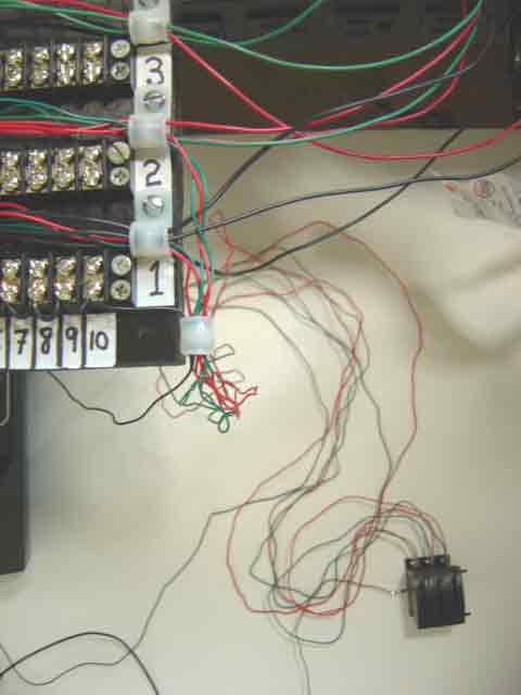
In Plate 254, we illustrated the two separate "flows" of wiring. The equipment wiring "flowed" from the power distribution center toward the layout, and the control wiring "flowed" toward a newly proposed location which we named the power and control center. In the accompanying picture, we have "channelized" the flow of control wires by attaching another 3/8-inch nylon cable clamp to the power distribution board (the new clamp is at the lower right of the board).
All six red and green wires serving the R044 lever bank have been directed through the new clamp. The black "common" wire, which connects to a constant-voltage AC supply, has also been directed through the new clamp. When 10 point motors have been installed, a total of 21 control wires will pass through this clamp: 10 red, 10 green, and one black "common" wire.
--more--
|
|
The location of the proposed power and control center has been simulated by placing one of the photographer's white backdrop panels about two feet below the baseboard level. This will not be the actual location of the power and control center - we simply wanted to show that the location of the control center is independent of the layout. Resting upon the backdrop panel is the R044 lever bank, where the six red and green control wires terminate. Just visible at the extreme left of the picture, mostly concealed from view, is the Railpower 1440 controller, which provides AC accessory power to a pair of wires: the black "common" wire and the brown wire from the R044 lever bank.
Part of the long black "common" wire can be seen at the lower left. Running near the "common" wire is a new length of black hook-up wire, which has recently been solder-joined to the short brown wire from the R044 lever bank, thus extending the "reach" of the brown wire. This extra "reach" permits the R044 lever bank to be emplaced at a more distant location from the Railpower 1440 than was permitted by the original short brown wire. The next two plates, which describe the appearance and functional details of the proposed power and control center, will explain exactly why the brown wire has been lengthened.
Go to top of page
|