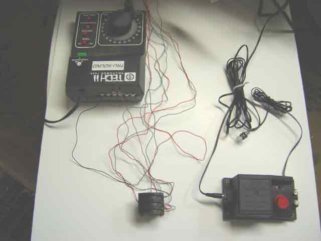
The 12-volt DC traction cable coming from the right-hand side of the R965 (lower right) has been temporarily disconnected from the R602 track clip and is lying loose on the photographer's backdrop panel. This was done to make it easier to compose the picture. The black "common" wire from Row 1, column 10 of the power distribution center has been attached to the third-position-from-the-left on the back of the Railpower 1440. Likewise, the brown wire from the R044 lever bank has been connected to the fourth-position-from-the-left on the 1440. These two positions are the AC "accessory" terminals of the 1440; they provide the same kind of current as do the AC binding posts on the R965.
Red and green control wires (three of each) from the power distribution center are connected to the bank of R044 lever switches. Finally, the short brown wire from the accessories position on the 1440 controller is connected to one end of the R044 bank. Not a single one of the wires in this picture is directly connected to a point motor, because point-motor wires are equipment wires, and equipment wires must all terminate at the power distribution center. In this picture, we are looking at the power and control center, where no equipment wires are allowed to enter. The only wires allowed here are power-source wires and control wires.
Go to top of page
|