For reference books and articles relating to these pages, see our bibliography
Are you getting tired of looking at trains? Try the Mad Toy Collector's exhibition, or visit The Heraldry Guy!
Searching for a particular topic in these pages? Try our subject index (updated continually)
It's all being made into a serialized movie! Click here to watch the movie episodes!
Go to the Next Plate Go to the Previous Plate Go to the Numerical Plate Directory

Plate 239:  Wiring the point motors through the distribution center, Part 17: all the jumpers have been installed, and we have continuity
(This plate added NOV 2003)

The bus is now fully wired, with all nine jumpers installed. The accompanying picture shows the result of a successful continuity test. The resistance tester indicates "zero ohms" (zero resistance) for the complete bus.

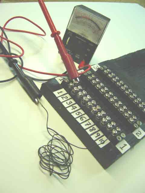
Observe that the red lead is clipped to one of the two terminal screws in row 1, column1, and that the black lead is clipped to the free end of the "common" wire. This means that current from the tester's internal DC power supply is running with zero resistance through all nine jumper wires as well as the "common" wire.