At the extreme left is a small soldering iron. This is a low wattage (low heat) soldering iron that is suitable for soldering electronic components and wires. The soldering iron's tip is resting upon a folding safety stand.
--more--
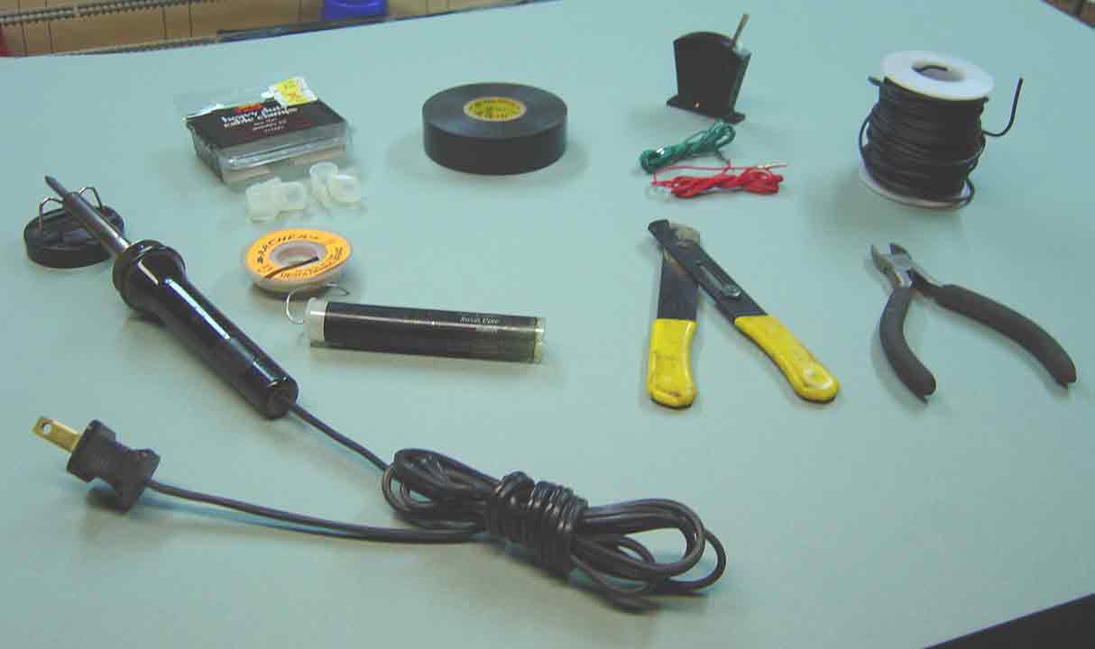
At the upper left of the tube of solder is an orange spool of "desoldering braid". This is a good item to have when doing electronic wiring. It is useful if you ever need to remove solder from an old connection. Why should you ever need to remove old solder? The usual reason is that you made a mistake in wiring, and soldered the wrong wires together. In order to remove old solder from a connection, you must heat the soldered connection with a soldering iron, in order to melt away the old solder. This can cause problems, because melted solder can drip or splash onto nearby connections or parts, possibly creating a short circuit after it cools.
The safe way to remove solder from an old connection is to heat the connection with a soldering iron while touching the tip of some soldering braid onto the soldered joint. When the heat from the soldering iron melts the solder, the braid will "soak up" the melted solder, thereby preventing the solder from falling onto exposed wires and parts. After the braid has soaked up the solder, you cut off the length of braid that was "soaked" and throw it away.
Above the spool of desoldering braid is a box containing nylon cable clamps. In front of the box are two of the clamps. These nylon clamps will be used to guide the wires from the point motors into orderly channels, so that the wires don't "dangle" all over the layout. The clamps will be fastened to columns or girders with the screws.
At the right of the cable clamps is a roll of PVC (polyvinyl chloride) electrical tape. After the stripped ends of wires are soldered together, the soldered joint should be wrapped with electrical tape. If this were not done, the exposed joint could touch another such joint in a bundle of wires, thus causing a short circuit.
At the lower right are two hand-tools. The tool with the yellow handles is a wire stripper. This tool is used to remove small lengths of insulation from wires that are going to be soldered together (this procedure is called "stripping"). The other tool is a small "diagonal cutter", which is used to cut off lengths of electrical wire.
At the upper right is a spool of electrical "hook-up" wire, commonly used for electronic wiring. This particular hook-up wire was selected because it has a greater current capacity than is required by the solenoids of the point motors. If we were to use hook-up wire that had insufficent capacity, the wire's resistance might create "voltage drops" that would "steal" power from the point motors.
Finally, at the left of the hook-up wire, is a Hornby R044 Passing Contact Lever Switch. Also shown are the red and green wires that were packaged with the lever switch.
Go to top of page