For reference books and articles relating to these pages, see our bibliography
Are you getting tired of looking at trains? Try the Mad Toy Collector's exhibition, or visit The Heraldry Guy!
Searching for a particular topic in these pages? Try our subject index (updated continually)
It's all being made into a serialized movie! Click here to watch the movie episodes!
Go to the Next Plate Go to the Previous Plate Go to the Numerical Plate Directory

Plate 209:  Constructing "E.L.L.Y." columns in the structural model, Part 5
(This plate added NOV 2003)

Here we have a sketch that contains all the measurements that were taken to "fix" the alignments and locations of three of the five E.L.L.Y. columns (see Plate 179 for a discussion of alignments and locations). To fix a column's alignment and location, a total of four measurements is sufficient. Two adjacent corners of each column are selected, then each of the two corners is measured in the east-west direction and in the north-south direction. This "fixes" the location of each of the two corners, making it easy to position the corners of corresponding miniature columns in the 1/12 structural model. This is how we created the "footprint" template shown in Plate 177.

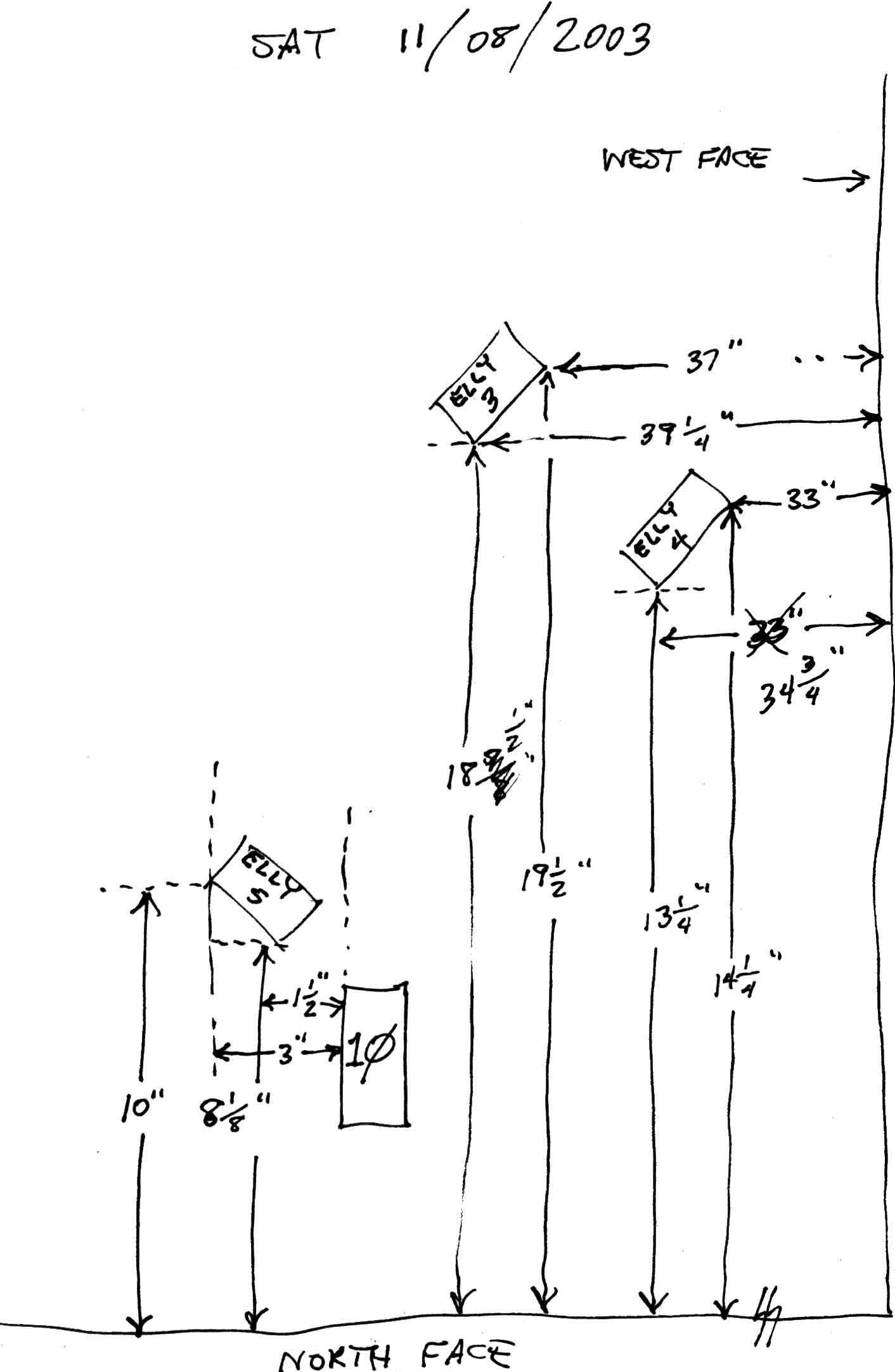
Only three of the five E.L.L.Y. columns were measured at this time (E.L.L.Y. 3, 4 and 5). This is because these three columns were highly likely to obstruct water-level tracks at this particular stage of planning. The other two columns, E.L.L.Y. 1 and E.L.L.Y. 2, are "out of the way" at the west end of the yard, so they were less likely to obstruct anything at this stage. Eventually, however, the structural model must represent every permanent structural element of the layout, including columns, girders, cantilever arms and roadbeds. This will be especially important when "scenic effect" (canals, hills, islands, retaining walls, streams, tunnels, waterfalls) begin to hide the layout's "skeleton". The structural model will always show us the "bone structure" that lies "under the skin" of the layout.

--more--
Observe that the north-south alignments and locations of all three columns were measured from the north face of the layout. East-west measurements for the alignments and locations of E.L.L.Y. 4 and 5 were taken from the west face of the layout. In the case of E.L.L.Y. 3 however, the east-west measurements were not taken from the west face of the layout, but from the east face of column 10. The reason for measuring E.L.L.Y. 3's east-west alignment and location from column 10 instead of the layout's west face was simply a matter of convenience. It was difficult to get an unobstructed east-west run of the measuring tape from the layout's west face to E.L.L.Y. 3, while column 10 was only an inch or so distant from E.L.L.Y. 3 in the east-west direction.

Go to top of page