For reference books and articles relating to these pages, see our bibliography
Are you getting tired of looking at trains? Try the Mad Toy Collector's exhibition, or visit The Heraldry Guy!
Searching for a particular topic in these pages? Try our subject index (updated continually)
It's all being made into a serialized movie! Click here to watch the movie episodes!
Go to the Next Plate Go to the Previous Plate Go to the Numerical Plate Directory

Plate 205:  Constructing "E.L.L.Y." columns in the structural model, Part 1
(This plate added NOV 2003)

If you examine the color-coded track schematic in Plate 129, you will see a written note near the bottom where the dotted pink outline meets the solid green outline. The note says "Water Level Begins". At this location, the water-level tracks seem to cross the throat of the embankment-level locomotive service yard. Actually, because of the differences in track elevation at this point, the water-level tracks are running under the tracks of the yard throat.

--more--
However, Plates 173 and 174 show that an embankment column was positioned close to this point after the track schematic was made (we refer to the short column at the right, near the letters APA on the baseboard). Does this "E.L.L.Y." (Embankment Level Locomotive Yard) column actually block the proposed tunnel? How can we be certain, one way or another, before actually attempting to lay down track that might or might not fit?

There does exist an inexpensive way to determine, before attempting to lay track, whether the E.L.L.Y. column blocks the way. The structural model, introduced in Plates 177 through 183, offers a means by which we can study obstacles like this before ordering a lot of expensive track that might not actually fit. We can simply construct 1/12-scale E.L.L.Y. columns in the structural model, and then trial-fit 1/12 scale paper tracks in the model, similar to the paper tracks in a concept model. In this way, if the column does indeed block the proposed tunnel, we can re-route the paper track and create a new schematic based upon the new track arrangement.

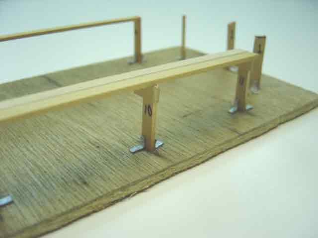
In order to place miniature E.L.L.Y. columns in the structural model, we must make exact measurements of the "footprints" of the actual columns and mark their positions in the model. First, we turn our attention to the structural model. The accompanying picture shows the model with numbers printed on the upper-level columns. These numbers correspond to numbers marked on the actual columns. Column 10, upon which the camera is focused in this "macro" shot, is the upper-level column that is closest to the yard throat of the locomotive service yard.

Go to top of page