For reference books and articles relating to these pages, see our bibliography
Are you getting tired of looking at trains? Try the Mad Toy Collector's exhibition, or visit The Heraldry Guy!
Searching for a particular topic in these pages? Try our subject index (updated continually)
It's all being made into a serialized movie! Click here to watch the movie episodes!
Go to the Next Plate Go to the Previous Plate Go to the Numerical Plate Directory

Plate 186:  Installing a surface-mounted point motor with an extension arm, Part 1
(This plate added NOV 2003)

The left-hand point that provides entry into the locomotive service yard is laid over a thick girder, so that installing a point motor beneath the roadbed is impractical. Therefore, the point motor will be surface-mounted, similar to the mounting for the upper-level point motor shown in Plate 99.

However, an important difference exists between the mounting method shown in Plate 99 and the method that will be required to surface-mount a motor near the service-yard point (see accompanying picture).

--more--
In Plate 99, the point motor was surface-mounted on the straight side of the point. The motor for the service-yard point must be surface-mounted on the curved side of the point, because there is no room for surface-mounting on the straight side, which is very close to the edge of the roadbed.

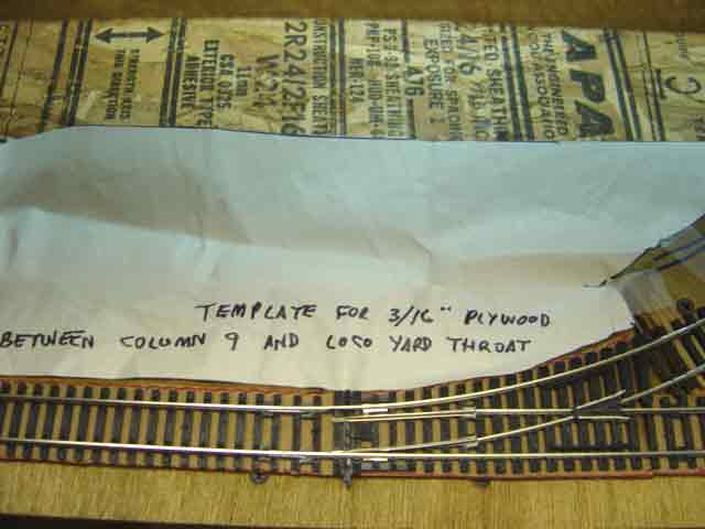
To provide plenty of room for the new point motor, we need to extend the roadbed several inches from the curved side of the point toward the south. The accompanying picture shows a paper template that was cut to the size and shape of the required southern roadbed addition (in this picture, south is "up", north is "down").

Go to top of page