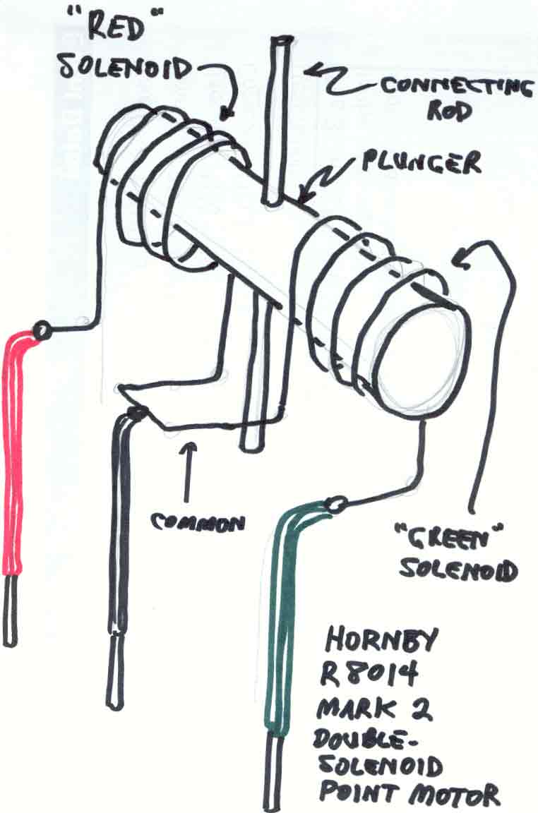
The "iron rod" no longer appears in this view; instead, we see a vertical "connecting rod". We also see that the vertical connecting rod is mechanically joined through the middle of a thick horizontal cylinder called the "plunger".
--more--
The purpose of the vertical connecting rod is to provide a mechanical connection between the point motor and the point. If the point motor is surface mounted, which is the only mounting we have discussed so far, the vertical connecting rod engages a horizontal sliding arm in the R8015 base plate. The R8015 sliding arm in turn connects to another horizontal sliding arm in the point. If the point motor is mounted beneath the roadbed (directly under the point), the vertical connecting rod pokes upward through an opening cut into the roadbed to engage the horizontal sliding arm in the point. The sideways motion of the vertical connecting rod thus causes an identical motion in the horizontal sliding arm of the point, thereby moving the point rails to either the "straight" or "curved" position.
(2) The plunger
The vertical connecting rod is affixed to a horizontal cylinder called the "plunger". The horizontal cylinder is called a "plunger" because it "plunges" through the center of either the "red coil" or the "green coil", depending upon which coil has current moving through it. For example (referring to the picture), suppose the current is moving through the red wire, then through the coil in the back, and then returning through the black "common" wire. The coil in the back will then force the "plunger" to "plunge" through the center of the coil in a direction away from the viewer. Likewise, if the green-and-black wires are conducting the current, the plunger "plunges" toward the viewer through the coil in the front.
(3) The solenoid coils
The two coils are actually called "solenoids". A "solenoid" is simply a pipe-shaped, hollow coil of wire that can cause a metal bar (a "plunger") to pass through the center of the coil when the coil is magnetized (a coil becomes magnetized when it conducts a current). The word "solenoid" refers to the shape of the coil; the word comes from the ancient Greek, and it simply means "pipe shaped".
In laboratory demonstrations of solenoids given in physics classes, an iron "plunger" is loosely placed inside a vertical solenoid coil, and then the current is turned on. When the current is conducted through the vertical solenoid, the plunger will be thrown clear out of the top of the solenoid into the air, finally landing with a loud noise on the professor's table, often waking up the entire class. In the Hornby point motor, the horizontal plunger is mechanically restricted from being "thrown clear".
It is very important to limit the amount of time that current is allowed to pass through a solenoid, because heat is generated by the passage of the current through the coil of solenoid wire. This is why we use a "passing contact lever switch" (the Hornby R044 unit). A passing contact switch permits current to move through the selected solenoid for enough time to "throw" the plunger, but not for enough time to heat the coil to a dangerous temperature.
Go to top of page