In this view, the black wire from the R8014 Point Motor has been temporarily connected to the black wire from the R965 Train
Controller. The black wire that extends downward from the point motor does not terminate in a connector. Instead,
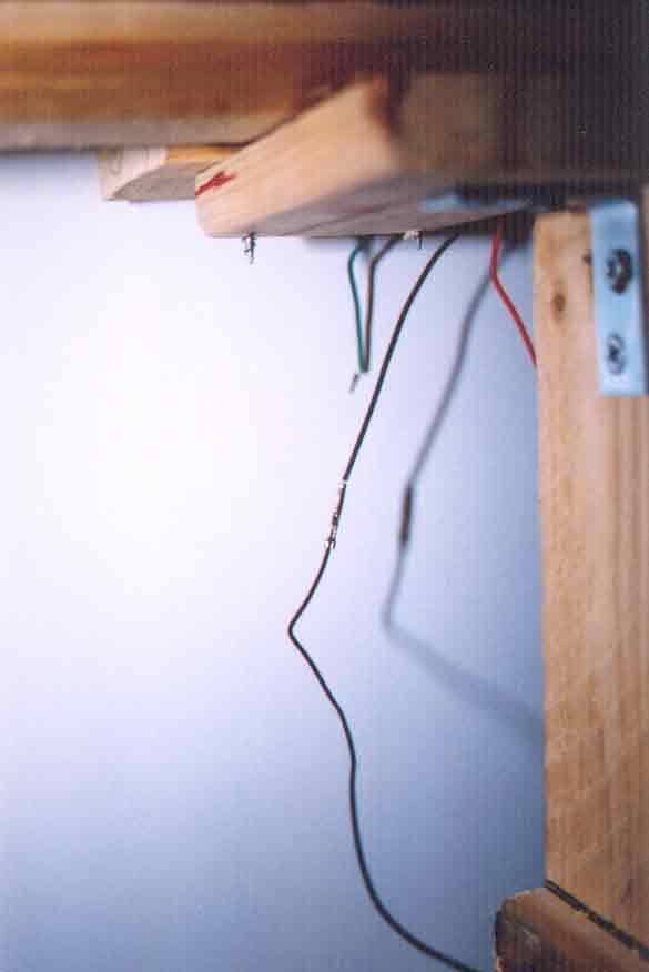
the black wire from the point motor terminates in a stripped wire end (see Plate 111). Note,
in Plate 111, that all three wires,
the red, the green, and the black that emerge from the point motor terminate in stripped wire ends. They are not
fitted with connectors, as are all the wires that come with the R044 Passing Contact Lever Switch.
Note: "stripped" means that a short length of insulation is removed ("stripped") from the end of a wire.
To accomplish the connection shown in this view, the stripped black wire end from the point motor was first bent
slightly in a shallow V shape, to provide some bulk. The V-shaped, stripped end of the wire
descending from the point motor was then pushed into the thin hollow plug
of the black wire from the train controller. Friction holds the two black wire-ends together. No soldering is done
at this time; this is only a test connection.
|
|