For reference books and articles relating to these pages, see our bibliography
Are you getting tired of looking at trains? Try the Mad Toy Collector's exhibition, or visit The Heraldry Guy!
Searching for a particular topic in these pages? Try our subject index (updated continually)
It's all being made into a serialized movie! Click here to watch the movie episodes!
Go to the Next Plate Go to the Previous Plate Go to the Numerical Plate Directory

Plate 51:  View looking northwest with the elevated roadbed fastened upon columns
(This plate added SEP 2003)

In this view, the entire loop of elevated roadbed has been fastened to the tops of supporting columns. The bottoms of the columns have been positioned within the blue marker lines which were traced when the roadbed had been tacked to the baseboard (see Plate 49). The columns, which were cut from furring strips, are fastened to the baseboard by means of metal corner brackets.

--more--
Column height:  mostly 12 inches, some 11-1/4 inches (note: columns are 11-1/4 inches high when they support a 3/4 inch girder positioned underneath the roadbed. Two such girders can be seen under the north and south runs of the roadbed).

Column width:   2-1/2 inches.

Column thickness:   3/4 inch

The bottom of the elevated roadbed is now uniformly at a height of 12 inches above the baseboard, in compliance with the second concept model. The Hornby track for the upper loop has been placed upon the roadbed for a trial fit.

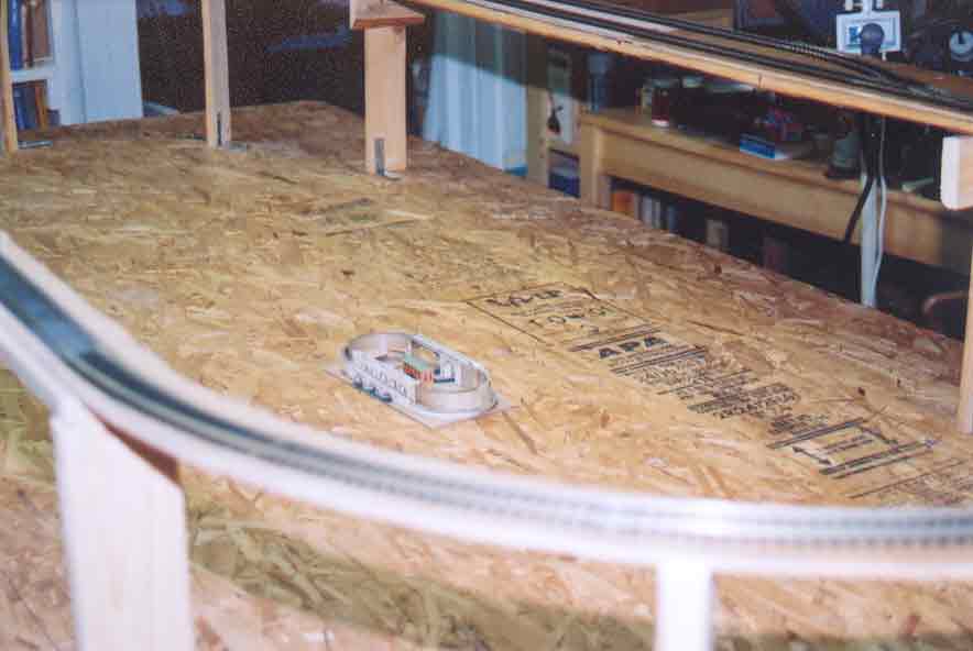
The second concept model can be seen at the center of the baseboard, correctly aligned with the actual roadbed. If you look closely at the concept model, you can see a small orange and green structure, which represents a possible future addition to the layout. The structure is based upon a picture of a 19th century canal warehouse, designed by Thomas Telford for the Ellesmere Canal Company in Shropshire, Britain.

Go to top of page