For reference books and articles relating to these pages, see our bibliography
Are you getting tired of looking at trains? Try the Mad Toy Collector's exhibition, or visit The Heraldry Guy!
Searching for a particular topic in these pages? Try our subject index (updated continually)
It's all being made into a serialized movie! Click here to watch the movie episodes!
Go to the Next Plate Go to the Previous Plate Go to the Numerical Plate Directory

Plate 49:  View looking southwest with the upper roadbed tacked directly onto the baseboard
(This plate added SEP 2003)

In this view, the elevated roadbed, which was scroll-cut from the plywood "quarter panels", is lightly fastened directly onto the baseboard by means of 4d (1-1/2 inch) finishing nails. The reason for doing this was to position the elevated roadbed upon the baseboard in accordance with the dimensions of the second concept model.

--more--
The concept model requires that the roadbed for the elevated loop should be about 5-1/2 inches inside the south face of the layout, and about 7 inches inside the north face, thereby providing room for the outer spiral track that will eventually descend to the baseboard.

To comply with these requirements, the elevated roadbed is lightly tacked to the baseboard, and then an outline is drawn with a marking pen around the inside and outside borders of the roadbed, resulting in a "projection" of the elevated roadbed upon the baseboard.

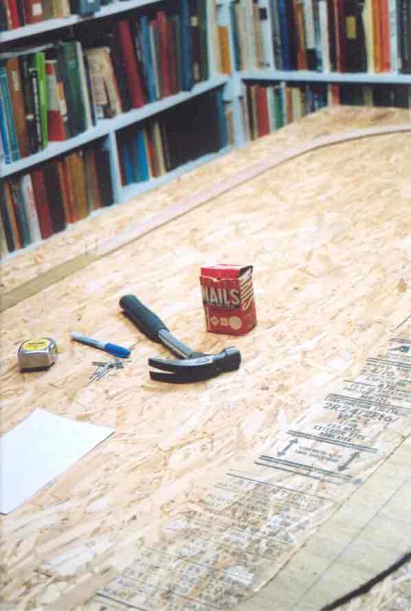
The tools for tacking and marking the roadbed appear in this plate: a 1-pound claw hammer, a 10-foot measuring tape, a broad marking pen, and a box of 4d nails. A rough pencil sketch of the roadbed's required placement relative to the baseboard is on the piece of notepaper shown with the tools.

Go to top of page