--more--
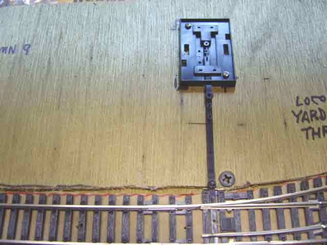
1. The extension arm has a socket at one end and an upright pin at the other end. The extension arm's pin must poke up through the round socket in the end of the baseplate's sliding arm. If you look closely at the extension arm, you will see two other pins sticking up near the pin that engages the socket. These extra pins are provided in case you want to shorten the extension arm. The shortening is done by cutting off pieces of the arm just short of a pin. You must not cut off the extension arm further than the innermost pin. If you shorten the arm by removing all three pins, the extension arm wiIl no longer be able to engage the socket of the baseplate. In this installation, we allowed plenty of room in the roadbed addition, so we didn't need to shorten the extension arm.
2. The extension arm has a round socket at the end joining to the point (bottom of picture). This socket fits down onto the pin that sticks up from the sliding element in the point.
Go to top of page