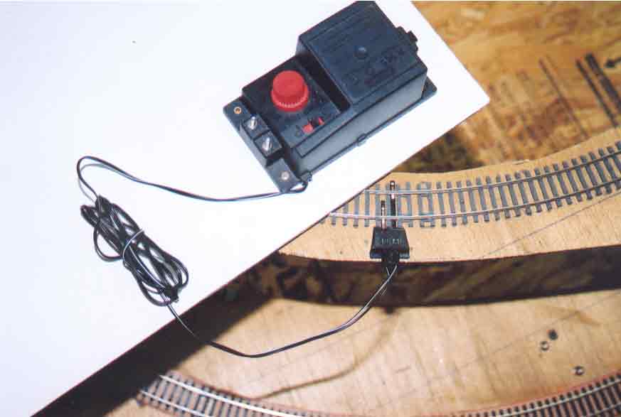
Standing upon the photographer's white backdrop panel is the R965 Standard Train Controller. Attached to the controller through a factory-wired internal connection is a 760-millimeter (30 inch) cable that carries the "traction" current to the layout's tracks (traction current is the current that runs the motors of trains, as opposed to accessories current, which provides power for miniature lights, switches, signals, etc.).
--more--
Note: newer electronic methods of speed control, which depend upon the transmission of encoded signals to specially-equipped model locomotives to increase or decrease their speed, do not apply to this layout at this time.
A small square black handle mounted upon a red slider can be seen at the lower right of the speed-control knob. This is the direction-control device. The direction-control device is a "double-pole double-throw" (DPDT) switch. Double pole simply means that the device is connected to both rails of the track, and double throw means that the switch has two operating positions. When the DPDT switch is moved fully to one position, the train will run forward. Likewise, when the DPDT switch is moved to the opposite position, the train will run in reverse. When the DPDT switch is in the center position, the train will not receive any current and will not move at all. Again, newer electronic methods, involving the transmission of encoded signals to specially equipped model locomotives to change their running direction, do not apply to this layout at this time.
This picture is unusual because the R965 controller and the R602 connecting clip are seldom seen so close together. The R602 is, of course, always connected to the tracks of the layout, but the R965 is usually mounted upon a control panel several feet away from the layout, thus affording the operator an overall view of the entire layout.
The two silver screws sticking up at the lower left of the red speed-control knob are terminal binding posts. Wires for point motors or other accessories are connected to these posts. These binding posts provide alternating current (AC), not direct current (DC). DC is required only as traction current for the tracks. When the power transformer (see Plate 105) provides the alternating current (AC) to the R965 controller, the R965 conducts the AC to the binding posts.
Go to top of page