Green wire in top socket of R044, red wire in bottom socket of R044
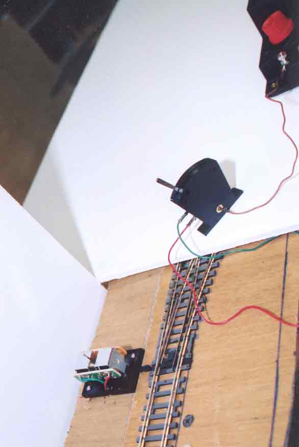
This view shows the third of four electrical tests of the R8014 point motor. The lever of the R044 lever switch has been moved to the left, and the R8014 point motor has responded by pulling the sliding arm of the R8015 base plate to the retracted position, thereby sliding the switch points so that a train will be directed to the "curved" track.
We therefore draw the inference that when the lever was moved to the left, the top wire that was plugged into the lever switch (the green wire) carried current to the green-wired solenoid, which pulled the plunger in a direction away from the tracks, thus retracting the sliding arm in the base plate.
Conclusion: when the R044 lever switch is viewed from the side where the brown wire plugs in, and the lever is moved to the left, the wire plugged into the top socket of the sloping side will conduct current. In this case, the green wire was plugged into the top socket, and the "green" solenoid was accordingly energized.