--more--
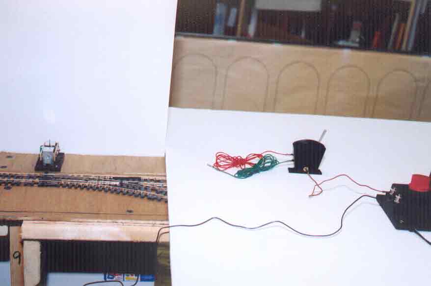
The red wire is plugged into the upper socket of two vertically aligned sockets in the sloping side of the R044 unit (the other end of the red wire is not yet connected).
(2) Green wire
The green wire is plugged into the lower socket of two vertically aligned sockets in the sloping side of the R044 unit (the other end of the green wire is not yet connected).
(3) Brown wire
One end of the brown wire is plugged into the socket in the base of the R044 unit, and the other end of the brown wire is screwed down to one of the AC binding posts of the R965 train controller.
(4) Black wire
One end of the black wire is screwed down to the other AC binding post of the R965 controller, and the other end of the black wire has been temporarily fitted to the black wire of the R8014 point motor (this fitting is not visible here; see Plate 112).
All that remains now is to connect the free ends of the red and green wires to the R8014 point motor.
Go to top of page